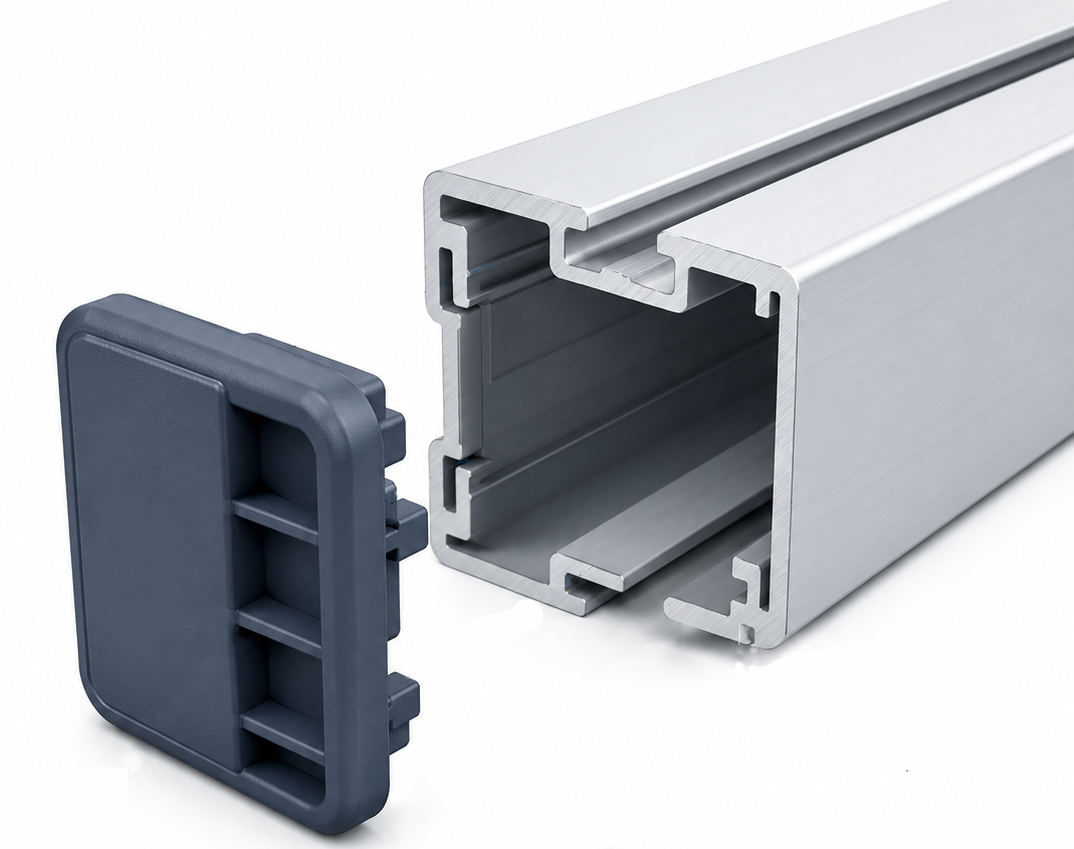
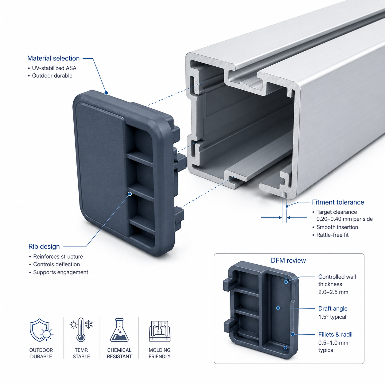
Selected Case Study | Nylon End Cap | Material Selection + DFM Risk Reduction Before Mold Build
Heavy-duty nylon end cap case study hero image
Case Study

Case Study: Heavy-Duty Nylon End Cap | Material Selection + DFM Before Mold Build

How Jeancen helped an Australian customer reduce material, fit, and tooling risk before mold build through PA66 direction setting, glass-fiber validation, moisture expansion assessment, and DFM optimization.

Nylon end cap product and engineering detail

Project Background

An Australian customer was developing a heavy-duty molded end cap for hardware use in a humid environment. The part also had a sliding-fit function, so material selection could not be based on strength alone. Long-term dimensional stability, wear behavior, and production practicality all mattered.

  • Humid-environment application
  • Sliding-fit requirement
  • Need to balance strength, wear, and dimensional stability
  • Customer initially uncertain whether PA6 or PA66 was the better direction

Project Specs

Engineers usually want a faster scan of the technical baseline before reading the full case narrative.

Material

PA66 + 30% GF for a humid-environment functional application.

Application

Heavy-duty hardware end cap with a sliding-fit function.

Key Challenge

Moisture expansion control, fit stability, and thick-wall sink-risk management.

Tooling Solution

2-plate mold, 1x2 cavities, 4 sliders, side gate, and optimized ejection strategy.

Main Engineering Challenge

The real challenge was not just “choose a nylon.” It was how to reduce risk across material, fit, moisture behavior, glass-fiber content, and mold manufacturability before the tool was built.

Challenge

Material Direction

The customer needed guidance on whether PA6 or PA66 was more suitable for the application and use environment.

Challenge

Glass Fiber Range

Once PA66 became the preferred material family, the next question was what GF percentage should be verified first.

Challenge

Pre-Mold DFM Risk

After material direction became clearer, DFM still had to address wall thickness, ejection safety, grip texture, and manufacturability.

Why We Recommended PA66

Based on the product information and service environment, our engineers recommended prioritizing PA66 over PA6. The decision was based on the application logic of the part, not on a generic material preference.

1. Better Mechanical & Thermal Performance

Compared with PA6, PA66 offered stronger mechanical properties, higher rigidity, better creep resistance, and better thermal stability for this application.

2. Better Dimensional Stability in a Humid Environment

PA66 also offered lower water absorption and better dimensional stability, which was important because the part had a sliding-fit function in humid use conditions.

3. Trade-Off Was Explained Clearly

We also made it clear to the customer that PA66 typically carries a higher material cost than PA6, and that market pricing would still depend on the actual sourcing timing.

Nylon end cap DFM and material validation detail

How We Narrowed the GF Range

We did not lock the answer too early. Instead, we recommended starting from two more realistic GF options based on assembly validation and engineering practicality.

  • GF-reinforced nylon was a suitable material family for this application
  • First-round validation should begin with two executable GF ratios
  • GF content could still be fine-tuned later within a ±5% range if needed
  • Critical fit dimensions could still be compensated by mold adjustment if necessary
  • For this part, wear resistance and self-lubrication mattered more than chasing theoretical dimensional perfection too early
We quantified likely dimensional change from water absorption, calculating an approximate 0.07 mm expansion on a critical 28.15 mm sliding-fit feature before any steel was cut.

How We Reduced Decision Risk Before Mold Build

Instead of asking the customer to decide based only on datasheets, we structured the project around real validation steps.

1

Material Recommendation

We recommended PA66 as the better base direction for this humid-environment sliding-fit application.

2

GF Validation Plan

We arranged sample validation using PA66 + 15% GF and PA66 + 30% GF so the customer could test against real assembly conditions.

3

Moisture Expansion Assessment

We evaluated the likely dimensional effect of water absorption before the mold design was finalized.

DFM Optimization Before Tool Build

Once the material direction was confirmed, we continued into DFM optimization to reduce mold manufacturing and trial-stage risk.

1. Functional Surface & Draft Strategy

The necessary draft optimization was completed, but critical fit surfaces were kept draft-free where needed to preserve functional performance.

2. Thick-Wall Risk Handling

The part had a local maximum wall thickness of 3.76 mm in a structural zone. Rather than over-reducing material blindly, we kept the required structural mass and planned to compensate shrink risk through process optimization, including longer pack time and higher holding pressure.

3. Ejection Safety Optimization

Because the final material direction was glass-fiber reinforced nylon, balanced ejection was critical. We removed a 0.2 mm bottom chamfer to improve blade ejector contact area and added a circular reinforcement feature for sleeve ejection without damaging structure.

4. Assembly Grip Improvement

To improve clamping stability in actual use, we recommended adding VDI18 texture on the side gripping faces to increase friction and reduce slip risk during assembly.

Final Result

After receiving samples and completing testing, the customer ultimately selected PA66 + 30% GF as the formal material direction.

  • PA66 was confirmed as a better long-term direction than PA6 for this application
  • GF range was narrowed through real sample validation
  • Moisture-driven dimensional change was assessed before tool build
  • Ejection safety and manufacturability were improved before steel cut

Why This Case Matters

The real value of this project is not only that the final answer became PA66 + 30% GF. The real value is that Jeancen helped the customer make safer engineering decisions before mold build, instead of leaving the risk to the trial stage.

  • Material risk was reduced before ordering steel
  • GF direction was narrowed through testing, not guesswork
  • Moisture expansion impact was evaluated early
  • DFM improvements reduced later tooling and trial risk

Working on a Nylon or GF-Reinforced Functional Part?

If your project depends on material choice, dimensional stability, wear behavior, fitment, or pre-mold DFM judgment, we can help review the main risks before the tooling decision is locked in.

Free DFM Review

Send your 3D file, drawing, or project details directly to our engineering team. We will review the key tooling risks and respond with initial engineering feedback.

Please include:

  • 3D file or drawing if available
  • Material or target application
  • Expected annual volume
  • Key tolerance, cosmetic, or assembly requirements
  • Main concern: warpage, sink marks, insert shift, gate marks, cost, or mold life
Email: sunny@jeancen.com
WhatsApp / WeChat: +86 187 5090 9501
Your project information is handled confidentially. NDA support is available upon request.
WhatsApp WhatsApp Us